18+ Relay 4 Pin Diagram
Panasonics EV-A Series can withstand up to an 8000A short circuit current rating. Ad Buy the Replacement Parts you need by category.

Foruly Universal Atv Utv Turn Signal Kit With Street Turn Signal Light Kit Rocker Switch Horn Usb Flasher Relay Fuse Line For Sxs Dirt Bike Polaris Rzr Can Am Kawasaki Golf Cart Dune
Door Locks - Nissan Maxima 1995 - 1997 Double Ground Pulse Relay Diagram.

. Pin 85 - Connect this pin to the ground or negative terminal on your power source. The control pin is connected to a switch or a control module that activates the relay. But still if you dont understand how to wire a 4 Pin relay then lets briefly discuss it here.
Relay can be the best option to control electrical devices automatically. The white wire attached to Pin 85 is the control circuit to the relay. Pin 87 - This pin is connected to the device you want to power on.
Similarly connect a fused wire which comes from the fuse box to the high amperage circuits terminal 30 of the relay. Web Here we will only discuss the relays connection points. Pin 30 - Connect this pin to the power source.
This video covers both 4 and 5 pin 12VDC relaysBest Connections - 12voltwireco. Find the Parts that Fit your Vehicle. A 5-pin relay is wired the same as a 4-pin relay.
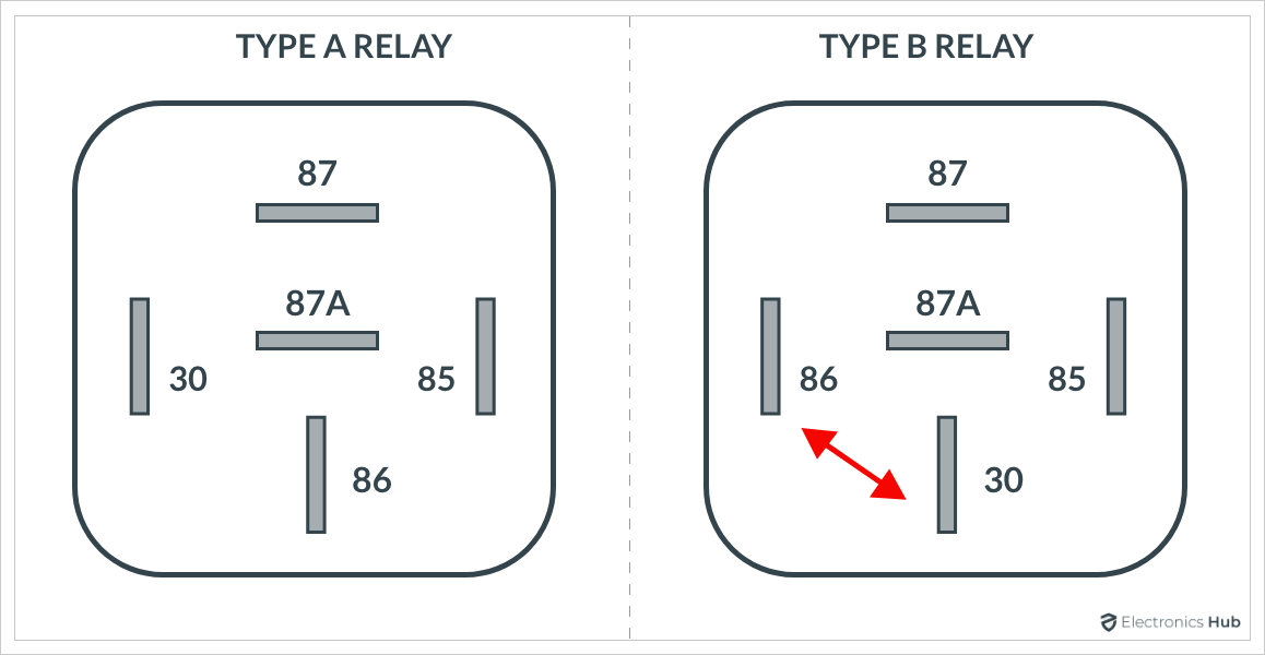
A 4 pin relay controls a single circuit whereas a 5 pin relay switches power between two circuits. Four-pin relays are commonly used in the application of fog lights LED lights and automotive electronics. According to DIN 72552 Standard each pin of a relay is numbered 85 86 30 87 and 87a.
Each of the 4 pins of the relay has different numbers mentioned on it that youll probably see on the one you have recently brought. Web Before we discuss troubleshooting relay-related wiring lets review. Wiring a four-pin relay is a simple three-step process.
Connect the other end of the switch to the coil terminal pin 85 or pin 86 of the relay. Why you need a relay is also covered. There are different kinds of relays for different purposes.
Door Locks - Ford Probe Type G 20. Here it is connected to pin 85. Web 5-Pin Relay Circuit.
By using a 4-pin relay you can safely control high-current devices. I know all about this stuff. Terminal 86 supplies power to the relays internal electromagnet.
Below is the circuit diagram of the four and five-pin car relays. 3 - Connection designation - relay control module on relay panel Shows the individual terminals in a multi-point connector. You need to know that a relay has two circuits a coil circuit also called a low.
The red wire is the battery power out to the fan Pin 87 once the relay is energized. Web Relays are one of the essential components of modern electrical systems. Web To wire a 4-pin relay you need to connect the common pin to the power source the normally open pin to the device you want to control and the normally closed pin to the ground or earth.
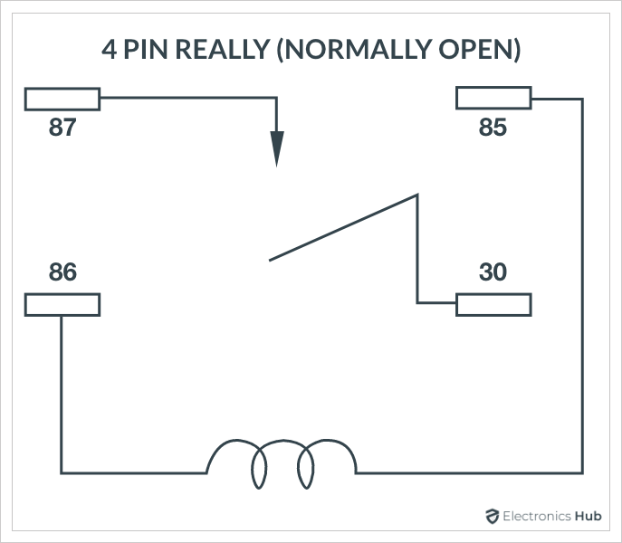
4 Pin Relay 4 pin relays use 2 pins 85 86 to control the coil and 2 pins 30 87 which switch power on a single circuit. Web When looking at a 4 pin relay switch diagram the most important parts to look at are the pins terminals and the control circuit. The pins are the small metal connectors that connect the relay to the load such as a light motor etc.
Connect Pin 85 to the ground. Door Locks - Dodge Caravan 2001 - 2005 Type H 19. Web A relay switch or a 5-pin is like a 4-pin relay with the addition of pin number 87a.
61 3 9521 6177. 2 pins 85 86 control the coil and 2 pins 30 87 switch power on a single circuit in a 4 pin relay. When the relay is energized ON pins 3 and 5 have continuity.
And you have finished wiring the four-pin relay for light. Web In this video I show you how to wire a 12 volt automotive Bosch style relay. 3 - PIN 4 - PIN 5 - PIN ISO STANDARDIZED RELAYS ISO relays were designed to try and standardize relay connections making it easier to test and design systems.
Web The green wire on the left side sends power to the blue wire on the relay socket Pin 30. Web The four-channel relay module contains four 5V relays and the associated switching and isolating components which makes interfacing with a microcontroller or sensor easy with minimum components and connections. Web Step 2.
Last week we talked about the standard DIN numbers used on relays and the incredible utility they represent. In any circuit with a DIN relay without looking at a wiring diagram you know that. Browse parts by category and choose the Replacement Parts for your vehicle.
There are two terminal blocks with six terminals each and each block is shared by two relays. The terminals are screw. Web Quick and easy way to wire a relay to safely power added lights.
5 pin is compromised of 3 main pins and an SPDT single pole double throw. A is nothing but an electromechanical switch in the sense that a mechanical contact toggles between ON and OFF states due to an electrical signal. Web Ⅳ 4 Pin Relay Wiring Diagram vs 5 Pin Relay Wiring Diagram 41 The Main Difference between 4 or 5 Pin Relays.
Ad Panasonics EV-A Series is suitable for various high voltage DC applications. Web The diagram on the side of this 4 pin relay represents everything about its connections. Web Page 3 4 RJ Relays 8 Amp and 12 Amp 1 pole and 2 pole Blade or PCB Terminals Page 5 RH Relays 1 2 3 and 4 pole 10 Amp Check button and indicator options Page 6 RU Relays 2 pole or 4 pole 10 Amp Page 7 RL Relays 1 pole or 2 pole 30 Amp DIN rail or Panel mount Page 9 RY Relays Small signaling relay.
61 3 9521 6133 Fax. The Circuit Protection Specialists. ISO relays are currently used.
This video will explain details of how to wire a relay. 2- Arrow Indicates wiring circuit is continued on the previous andor next page. Web Heres a simple way to wire a 4-pin relay.
The terminals are the larger metal connectors that connect the power source to the relay. Web just an idea on how to wire each relay upfeel free to ask me anything. Web Learn how to wire a 4 or 5 pin relay with our wiring diagrams and understand how relays work.
Connect a 12V battery to Pin 30 of the relay via fuse. Web The diagram above is the 5 pin relay wiring diagram. There are 2 types of 4 pin relay.
These include Pins. 4 - Diagram of threaded pin on relay panel. Connect terminal 87 of the high amperage circuit to the headlight.
Web Indicates location on relay panel. Web Relay wiring diagrams of dozens of 12V 5 pin SPDT automotive relay wiring configurations for mobile electronics applications. The black wire on the fan connector and socket Pin 86 provides grounding for the relay and fan.
It can be used for various switching. Connect The Relays High Amperage Circuit. Connect one end of the switch to the positive power source.
Web When the 5-PIN relay is de-energized OFF pins 4 and 5 have continuity. Contact 24 on terminal on relay panel. How to Wire an 8-Pin Relay.
The difference is that when a current isnt sent through pins 85 and 86 rather than breaking a single circuit the 5-pin relay will switch to the circuit connected to pin 87a. We use relays generously in automobiles and measurement equipment power supplies home automation systems and many more. Connect the ground to the remaining end pin 86 or pin 85 of the relay.
This is the power that will be used by the relay to switch the device on.

3 Lead Led Light Bar Rocker Switch Relay Wiring Harness Kit Remote Control 12v Ebay
Relay Wiring Diagram 4 Pin 5 Pin Automotive Relay Electronicshub

Kampot Power Plant Cambodia Diesel Power Station Pdf Electrical Wiring Relay

Razor E100 Scooter 24 Volt Controller With 7 Connectors For Razor E100 And E125 Versions 10 E150 Versions 1 E175 Versions 18 Razor Part W13111612015 Amazon De Sports Outdoors

Finger Plate Black Cast Iron Push Plate

Sti Ra Fog Light Iw Sti Forum

Mfj Auto Electrical 4 4 Pin Relays Use 2 Pins 85 86 To Control The Coil And 2 Pins 30
How To Use A 4 Pin Relay Quora
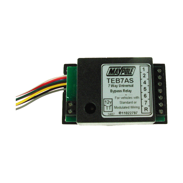
Maypole Relay 15a 7 Way Bypass Dp Euro Car Parts
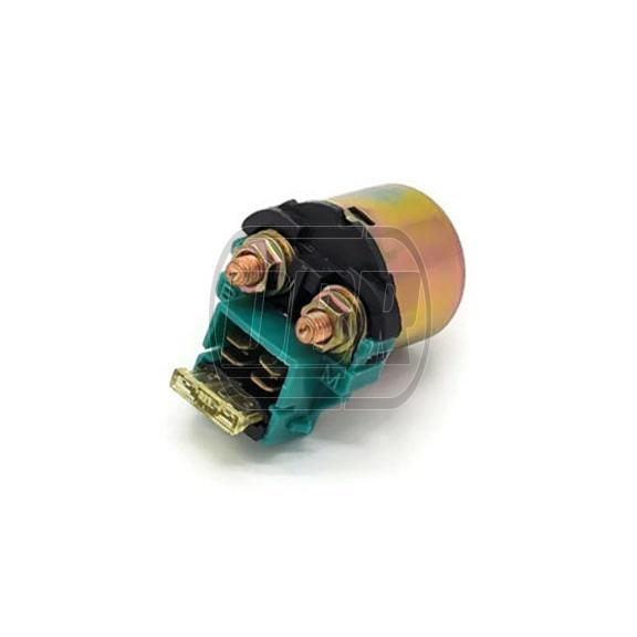
Starter Relay Solenoid Fused 4 Pin Dbracing
Relay Wiring Diagram 4 Pin 5 Pin Automotive Relay Electronicshub

Made This Power Relay Panel For My Truck R Trucks

Image Result For Relay Wiring Diagram 5 Pin Electrical Circuit Diagram Circuit Diagram Electrical Diagram
Led Flasher Relay Honda 4 Pin Free Uk Delivery Flexible Ways To Pay M P

W D Drawing For Power Cum Plc Panel For Td 80 Pdf Pdf Relay Electrical Wiring

How To Wire Relays Light Flash Two Wire German Vehicles Negative Output From Alarm Keyless Entry Dual Make Spst Relay Relay Diagram Negativity

14 Pin Relay Wiring Diagram Base Wiring Diagram